Circuit Design
How to Design Basic Electronics Circuit using Diode, Precision Potentiometer, Capacitor etc
Circuit Design is one of the basic and yet technical aspect of electronics in our schools and life as an electronics hobbyist. As we shall be working with component such as Diode anode cathode,Principles of Diode forward bias, Diode characteristic, Capacitors, Wire Wound Resistors and Precision potentiometer.
The art of electronics and ability to imagine or been creative is an important skill in science. Innovations, ideas, research and persistent has brought about the existence of certain component in engineering and science as a whole. Today, I will be giving you a concept of knowing what you want to do and how to go about it.For instance, you came back home after the day’s job, tired and hungry. Reaching out to the wall switch to put on your lighting system and television set, it seems it’s another form of work. The thought of having a system where you could just be on your sofa and put on your room lighting system, security light outside, television set and so on.
First, in wanting to construct a unit that will receive infra-red (IR) signal from your TV remote control, you need a component that can receive these IR signal (Infra-red ray), then convert it to switch ON or OFF a relay. Since a relay can be use as a switch, the relay will now serve as the contact-maker or switch-operator for you.Having gotten an idea of your intention, its time to look for these component. The first stage is the stage that will receive the IR ray, but this stage cant stand alone without a “Pulse stretcher”. A Pulse stretcher is a monostable multivibrator. Once triggered, it remains ON for duration of time determined by the RC-network known as the frequency determining network. This is necessary because the stream of pulse “IR ray” coming from the IR transmitter in the TV remote is a stream of multiple rays oscillating from 300Hz up to 33 KHz depending on certain factor. BUT, we only needed ONE ray to drive the next stage. So, we improvise a stage that will help us eliminate other rays while allowing ONLY on ray to pas through. The output of the second stage (Pulse Stretcher) is then connected to a unit that will be doing the changing of “state” for us. It’s called A Bistable Multivibrator. We will use a decade counter CD4017 connected in such a way as to serve as a Bistable Multivibrator for us. Such that, when it receives a pulse of IR ray, its OUTPUT will be High (ON) or Low (OFF).
This On or off state will be connected to the base of a transistor that will energize a relay. GBAM!!! Simple? Let’s find out
- Infra-Red Receiver
Infra red receiver is common in the market. Below is a popular type of IR Receiver and its pin configuration (arrangement).

As seen from the diagram above, the first pin from your left with the device facing you directly is Pin 1 (Connected to GROUND), Pin 2 (Connected to Positive Supply- VCC) and Pin 3 (Connected as output to the next stage) Output.
So, from my diagram, the terminal of the NAND gate i used, the first pin connected upward is the Positive VCC, The centre connecting to the next stage is Output while the last terminal going Ground is Ground.
The first terminal or pin is tagged “Pin 1”. Pin 1 is the “Ground”. So, during our construction, we will connect pin 1 to the ground or neutral potential of our power supply unit (Battery).

Next, Pin2 is “+V” known as the positive terminal or positive pin for our power supply unit. Also, we shall connect a regulator (Zener Diode) rated at 5.1V to provide a stable voltage not beyond 6V.
Next, Pin 3 (Output) will be connected to the next stage as our source of signal input for that stage.
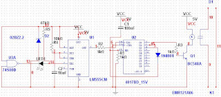
Below is a circuit diagram with precise and correct component values that has been assembled and tested for quality reason to enable you put something of this form together. I shall be using “Multism 10” in drawing the circuit diagram.

I was unable to get the symbol of IR receiver in Multism 10 component list, so i used a NAND-gate logic circuit symbol in representing IR Receiver. ok! For those of us that doesnt known what a NAND Gate symbol is, its the symbol at the begining of the diagram with a little circle ball at the back connecting to the next stage been the Pulse Stretcher.
Please note that, D1 and K1 are poitns where you will connect your load or socket or Bulb, while the other end is your source of power say PHCN as the case may be.
Dont forget to connect pin 8 of CD4017 to ground and pin 14 to supply (VCC). Feel free to leave your questions as the need arise.
No comments:
Post a Comment
We Love comment(s) or question(s). Please feel free and hit us!